
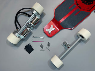
When you purchase a new gear drive kit from Defiant, it comes fully assembled and ready to ride. All you really have to do is bolt it onto your deck, connect the motors to your ESC, run your motor detection process and adjust some ESC settings if necessary. The hard and messy parts such as greasing the gears, bolting on the motors, and applying appropriate adhesives on bolt threads and motor shafts is done for you.
In this post we’ll walk you through each step of the installation process and even touch on general maintenance and replacing your gear grease.
Required Tools
- 3/8" wrench for the truck bolt's nuts
- Appropriate driver (hex head, Philips, etc) for the truck bolt heads
Installation
Because the drive system comes fully assembled with matching front truck and wheels installed, installing it is just as simple as bolting on any other set of trucks.
Before installation, make sure you have the riser pads you want to use (if any), x-plates or shredlights brackets if you’re using those, and truck bolts handy. You want the truck bolts to be just long enough to expose a few threads once the bolt goes through any brockets, the pads, and the deck when the nuts are tightened down.
Our trucks are reverse kingpins, so begin by lining up the front truck’s bolt holes with the bolt holes in your deck and risers, with the kingpin nut facing toward the nose of the deck. Push the first truck bolt through and finger tighten the nut. Then choose the opposite diagonal corner for the next bolt, push it through, and finger tighten the nut again. This will make lining up the remaining two bolt holes easier. Install the remaining two bolts the same way. Once all four bolts are in, tighten all the way down snuggly using a wrench and the appropriate manual or powered driver for your bolt heads.
The rear truck includes the motors and gear drive assembly, and as mentioned before the drive system is pre-installed, so installation is as simple as the front truck. Begin by lining up the truck bolt holes with the riser and deck bolt holes, with the motors and kingpin nut pointing toward the tail of the deck. Repeating the bolt installation steps from the front truck, pass the first bolt through then finger tighten the nut. Do the same first with the bolt hole diagonal to the first one, followed by the other two. Finally, tighten all four nuts down completely with a wrench and appropriate driver for the bolt.
Motor connections and ESC configuration and compatibility
Our motors come with standard 4mm bullet connectors on the phase wires and the typical 6 pin JST connector for sensors. They are compatible out of the box with most if not all VESC based ESCs, but phase lead connector size will vary between models and you will want to double check the pin outs for your sensor connectors. For example, no modifications are necessary for the Lacroix Stormcore or Trampa MkIV, but you will need to swap phase lead connectors if using a MakerX DV6 or BKB Xenith.

Once the motor connections are made you can power up the ESC and run motor detection as you usually would if necessary. If using a VESC compatible ESC, that would mean using VESC Tool, FreeSK8 Mobile, or other VESC compatible app on your phone or laptop.
With regard to settings, that will vary depending on your battery and ESC. There is a lot of documentation and discussion on the internet regarding the methods used to arrive at appropriate settings, so we won’t get into that here. As a starting point, our boards currently use a 12S5P Molicel P42A battery pack and a Stormcore 60D+, so we use the following motor settings:
- Motor Current Max: 75
- Motor Current Max Brake -70
- Battery Current Max: 65
- Battery Current Max Regen: -15
- Absolute Max Current: 200
- Slow Abs Current: on
Dashboard Configuration
If using a dashboard such as a Davega or a phone app with telemetry, you’ll want to use the proper settings to get accurate results. Below are the relevant specs for the drive kit as it comes in the box:
- Gear ratio: 2.22 or 27/60
- Wheel height: 100mm
- Motor poles: 14
- Motor KV: 190
If you’re using compatible wheels of a different height, don’t forget to update that.
Maintenance
General maintenance for your Defiant gear dive system is minimal. It is recommended to occasionally check for loose bolts on the gear boxes, and to always keep your axle nuts tight enough to eliminate any sideways movement of the wheel but still allow the wheel to roll freely.
On occasion you may decide to change or just check the gear grease in your drive system. To access the gears, you must first remove the wheel followed by the gear cover. Remove the wheel by loosening and removing the axle nut, then sliding the wheel off off the axle and drive pegs. Once the wheel is removed, remove the gear box cover using a 3mm hex key to loosen the four bolts holding it on. Three of the bolts are on the wheel side toward the rear of the board, and there is one more on the board side toward the nose. Once these four bolts are removed, gently detach the gear box cover and the gears will be exposed.
You may now use your favorite method for removing the grease and cleaning the gears. We have found that wiping off the excess with disposable rags then rinsing off the remaining grease with WD-40 works well, although very messy. Resist the urge to use strong degreasers, as it may also start removing the anodize on the aluminum. You will want to do this in a well ventilated area or outside.
After the old grease is removed, replace it with your favorite gear grease. We recommend Lucas Oil Red ‘n’ Tacky. Using a popsicle stick or similar applicator, smear the new grease into all of the gear teeth like cake icing, and glob a little bit up in the gaps where the two gears begin to mesh.

After applying the grease, use a rag or paper towel to wipe along the edges of the gear drive mounting plate where the first three threaded bolt holes are. Once the edge is nice and clean, put a tiny drop of blue threadlocker such as Loctite 242 into the bolt holes with the threads and wipe off any excess on the surface of the plate. You will also want to do the same with the gear box cover for the final threaded bolt hole located on it after you clean it as well.
Replace the gear box cover and insert and tighten down the bolts firmly. You will most likely have gear grease squeezing out of the crack where the cover meets the mounting plate. Once the bolts are tightened you can use a rag or paper towel to wipe off the excess that squeezed out. Allow the threadlocker to cure for about a day before riding.
Conclusion
We hope you found this guide helpful. Any questions can be directed to support. Happy riding!